
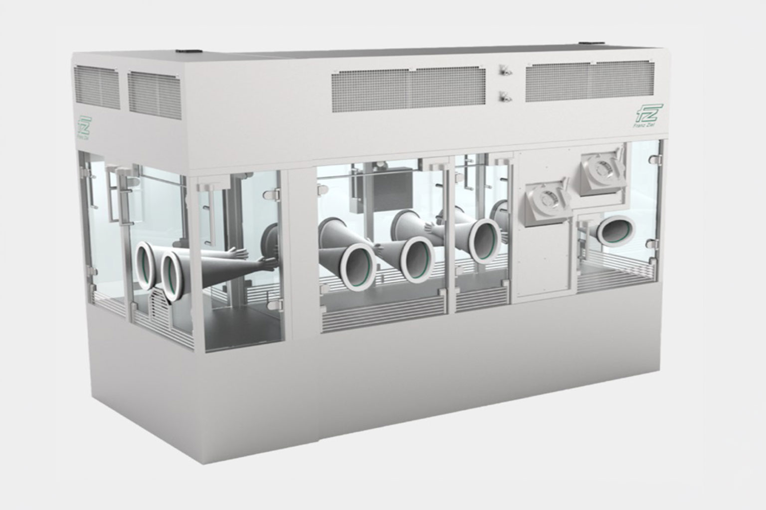
Ceiling-mounted air intakes on open Restricted Access Barrier Systems disrupt critical airflow patterns in Grade B cleanrooms. Here’s why — and what the right answer looks like.
How much air is actually moving?
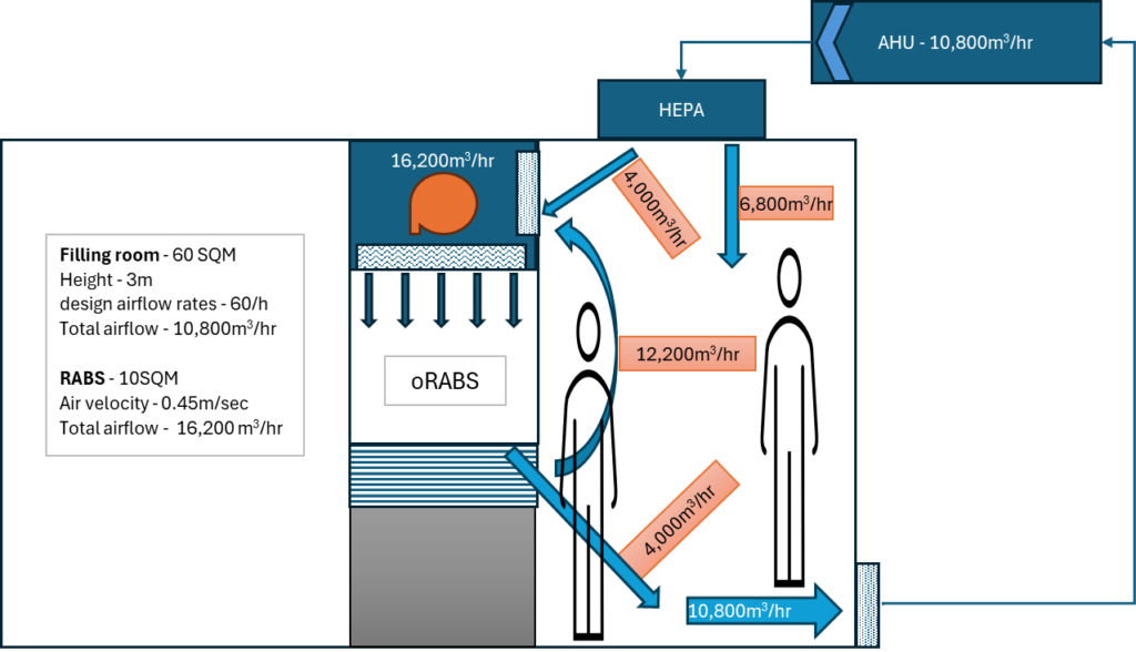
An oRABS system experiences significant air demand because its entire ceiling is equipped with HEPA filters operating at an airspeed of 0.45 m/sec. Each square metre of such a filter requires an intake of 1,620 m³/hr. With a typical filling-line footprint, the oRABS therefore has a substantial impact on the airflow within the surrounding filling room.
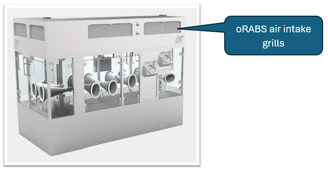
The problem with ceiling-level intakes
When the oRABS pulls its supply air from near the ceiling of a Grade B cleanroom, two things go wrong simultaneously:
- Air escaping from the oRABS vents is drawn upwards, resulting in airflow moving in the wrong direction. In a representative Grade B installation this can amount to ~12,200 m³/hr travelling counter to the intended downward flow pattern.
- Air supplied by the room’s own inlets — whether through direct HEPA filters or swirl diffusers — is drawn straight toward the oRABS intakes rather than washing the room and removing contaminants. In the same example, ~4,000 m³/hr out of a total room supply of ~10,800 m³/hr is effectively bypassing its cleaning function.
In other words: the oRABS appears to be doing its job, but the room around it is being short-circuited.
Why these systems are still being built
Despite the issue, oRABS vendors continue to manufacture systems with ceiling-level intakes because they are simple to install and cost-effective to deliver. The downstream consequences — disturbed Grade B airflow patterns — are absorbed by the end user, often unnoticed until commissioning.
What the right design looks like
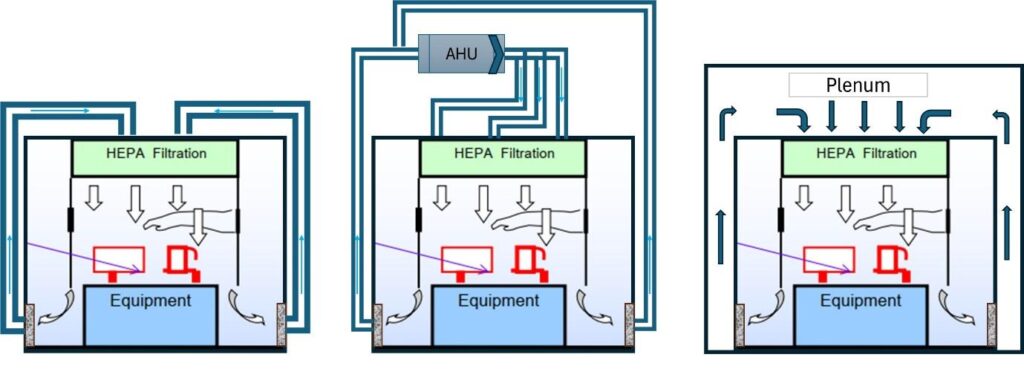
The preferred solution is to supply the air from the technical area above the room rather than from the room itself. Several practical options exist:
- Direct ducting — return air ducts routed from the technical floor down into the oRABS intake
- Dedicated AHU supply — air supplied directly from an air handling unit, bypassing the Grade B room
- Plenum — a sealed plenum above the oRABS that decouples its air demand from the room atmosphere
Any of these configurations eliminates the two failure modes above and restores the intended Grade B airflow pattern.

This is not a risk-assessment problem
A poor design of a Grade B environment is not something that can be compromised or resolved by a risk assessment — the influence of a poor design may extend into areas that simply cannot be characterised after the fact. The right place to fix this is on the drawing board, before the system is built and commissioned.

